|
|
|||||||||||||||||||
|
|
|||||||||||||||||||
Technical |
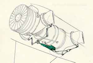
How the Harrier hoversAlthough it took a lot of testing to get the Harrier family to work effectively, the fundamentals of vectored thrust are essentially very simple. During wing-borne flight the Harrier is identical in operation to a conventional aircraft, with the usual control column, rudder pedals and throttle used for piloting. The following description is an outline of how the Harrier differs from a conventional aircraft, namely in the realm of jet-borne flight. Engineering and piloting differencesThe key difference between the Harrier and other combat aircraft is the Pegasus engine. This is a low bypass-ratio turbofan that is similar in operation to other such engines, with the additional feature of four rotating nozzles through which the engine's fan and core airflows exhaust (Fig. 1). These four nozzles can be rotated through an arc of 98.5 degrees, allowing the engine's thrust to be applied from directly aft (in conventional flight) to straight down (for hovering) to slightly forward (for flying backwards!). The range of nozzle movement can be seen in Fig.5 below. Although this shows the nozzles being moved by hand, they are normally actuated using a pneumatic motor operated by engine bleed air. This motor drives a number of shafts and chain drives (Fig.2) to ensure that all nozzles operate in unison - any difference would lead to a rapid loss of aircraft attitude and control.
To control nozzle angle, the pilot is provided with an additional lever alongside the conventional throttle (Fig. 3). This lever is used to select the appropriate nozzle angle for the desired mode of flight, with the addition of an adjustable stop for short take-off allowing the pilot to accurately select the correct nozzle angle during this type of operation. There is also a fixed stop for vertical take-off, ensuring that the nozzles are truly vertical in relation to aircraft attitude. Using the throttle, the pilot needs to ensure that engine thrust provides sufficient jet-lift to keep the aircraft aloft before 'down' nozzle is selected. However, this interaction between the amount of thrust and its direction is the only major piloting difference between the Harrier and other aircraft, albeit one that needs careful training to master.
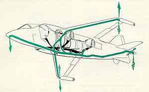
In addition to the vectoring engine nozzles, the Harrier also requires a method of controlling its attitude during jet-borne flight, when the normal aerodynamic surfaces are ineffective. To this end, a system of reaction control nozzles in the nose (blowing down), wingtips (blowing up and down) and tail (down and lateral blowing) are fitted to the aircraft (Fig. 4). These nozzles are supplied with high pressure air bled from the engine and are operated by the normal flying controls. Pilot command operate valves in each nozzle that allow powerful jets of compressed air to provide the desired movement in pitch, roll or yaw. The system is energized once the engine nozzles have been partially vectored, with the amount of engine bleed air increasing with reducing airspeed, allowing for the seamless passing of authority from aerodynamic to reaction controls. This frees the pilot from any excessive workload during the transition to and from conventional flight, increasing aircraft safety. The end result of this essentially simple approach to V/STOL flight can be seen in Fig. 6. - now you know how it is done!
The two animations above are taken from the 'Jet Pilot' video - available from www.gulture.com. Both are reproduced here by kind permission. |
|